

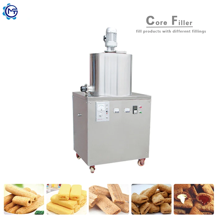
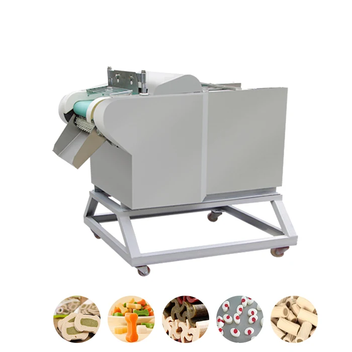
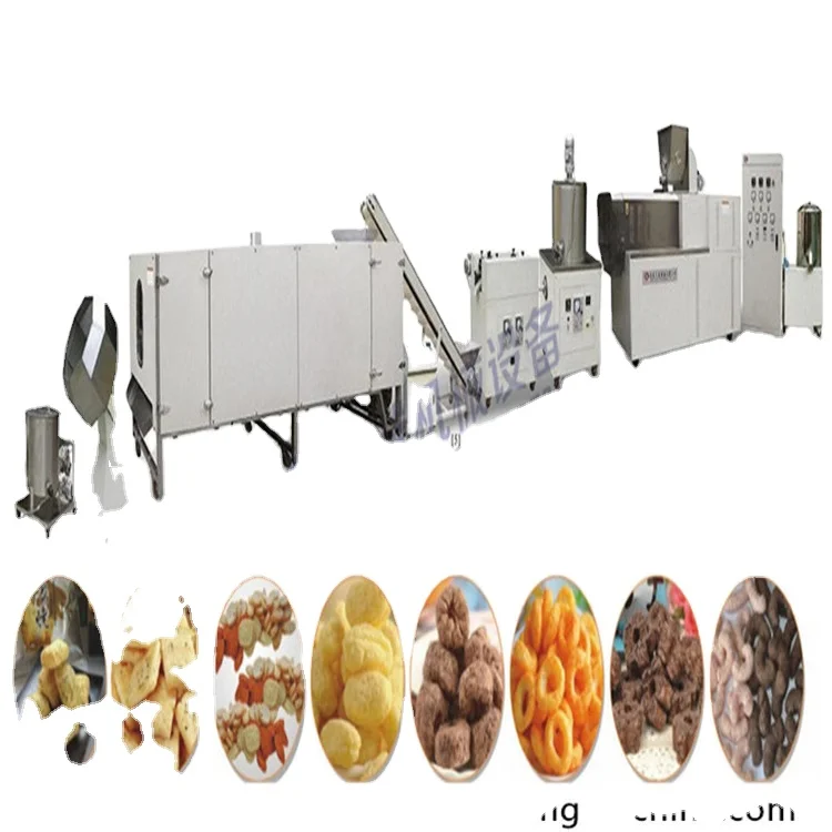
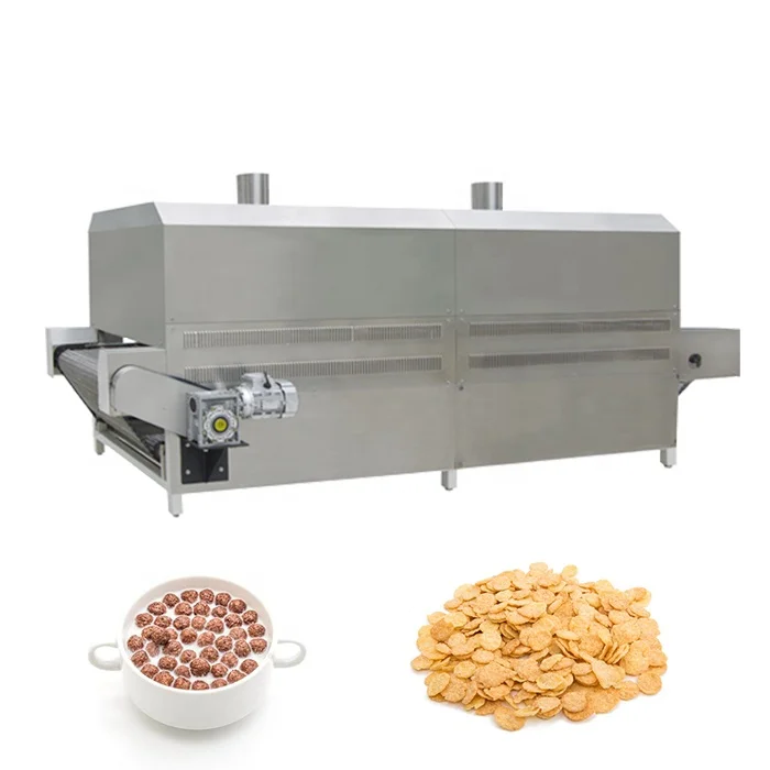
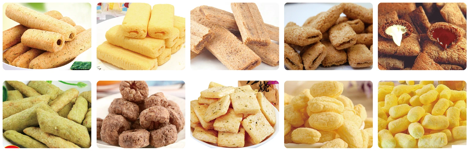
Core Filling Puff Snack Food Extrusion Line, three capacity tiers (MT65/MT70/MT85), turnkey configuration from mixing to packing — engineered for complete snack food production integration.
- Screw configuration and die design matched to your raw material and target core-filled texture
- Dryer length and layer customized to product moisture specification, with automatic or semi-automatic flavoring systems for sugar, oil, and powder seasoning
- Full line throughput verified across every station before delivery, eliminating cross-vendor bottleneck risk
Layout design, phased installation schedule, and operator training included with lifetime maintenance support from a single supplier.
Description
Throughput-matched line integration — Every station from mixing through flavoring is sized to the same output target before steel is cut, so no single machine bottlenecks the rest.
Technical Specifications
| Parameter | Value |
|---|---|
| Product Type | Core Filling Puff Snack Food Extrusion Line |
| Model Options | MT65, MT70, MT85 |
| Screw Type | Single screw (double screw extruder also referenced in source — verify configuration) |
| Installed Power (MT65) | 70 kW |
| Real Power (MT65) | 40 kW |
| Output Capacity (MT65) | 100–150 kg/h (basis not stated in source — confirm raw material / moisture / product format) |
| Overall Dimensions (MT65) | 20000 × 1200 × 2200 mm |
| Installed Power (MT70) | 100 kW |
| Real Power (MT70) | 70 kW |
| Output Capacity (MT70) | 200–240 kg/h (basis not stated in source — confirm raw material / moisture / product format) |
| Overall Dimensions (MT70) | 25000 × 1500 × 2200 mm |
| Installed Power (MT85) | 200 kW |
| Real Power (MT85) | 150 kW |
| Output Capacity (MT85) | 300–400 kg/h (basis not stated in source — confirm raw material / moisture / product format) |
| Overall Dimensions (MT85) | 30000 × 3500 × 4300 mm |
| Line Stations | Mixing, extruding, shaping, cutting, drying, flavoring (full automatic one-pass operation) |
| Flavoring System | Semi-automatic or automatic; supports sugar, oil, and powder seasoning |
| Dryer Configuration | Customizable length and layer based on product type |
| Control System | Not specified in source (verify against manufacturer catalog) |
| Voltage & Frequency | Not specified in source (verify against manufacturer catalog) |
| Warranty | 24 months, lifetime service |
| Certification | CE (electronic edition available) |
Application Suitability
| Application | Material or Output |
|---|---|
| Core-filled puff snacks | Corn grits, rice flour, wheat flour with cream or chocolate filling |
| Puffed extruded snacks | Corn, rice, multigrain blends in ball, tube, or ring shapes |
| Fried snack pellets | Potato starch, corn starch, wheat flour for secondary frying |
| Artificial rice | Rice flour, corn flour, fortified blends shaped into grain form |
| Breakfast cereal pieces | Oat, corn, and wheat formulations for ready-to-eat cereal |
What a Rated Capacity Figure Leaves Out About Your Core Filling Puff Snack Extrusion Line
A capacity number means nothing unless the dryer, flavoring drum, and conveyor are all rated to move the same volume.
I once watched a snack line in the Pearl River Delta sit idle for two full shifts because the single-screw extruder was purchased separately and its output rhythm never matched the flavoring drum downstream. Puffed pieces piled up on the belt, cooled into a solid mass, and had to be cleared by hand before anyone could re-tune the parameters. That kind of mismatch is invisible on a quotation sheet. When a Core Filling Puff Snack Extrusion Line turnkey project is scoped, every station — from batching to packing — needs its throughput calculated against the same raw material moisture and target product density. [NEED_CITE: typical causes of throughput mismatch in extrusion lines]
Layout Engineering Before Steel Is Cut
A Core Filling Puff Snack Extrusion Line turnkey project starts with a factory footprint drawing, not a catalog page. The layout accounts for the extruder footprint, dryer length, and flavoring drum clearance so that operators have walkways and maintenance crews can reach drive motors without dismantling adjacent equipment. Utility drops for water, compressed air, and electrical circuits are plotted against each station’s actual draw rather than summed from nameplate ratings.
Phased Installation and Commissioning Schedule
Large lines do not arrive on a single truck. Equipment is typically grouped into mechanical, electrical, and pneumatic packages that arrive in sequence. The extruder and dryer sections go in first, followed by the flavoring and packing stations once the upstream equipment has passed its wet-run test. This phased approach lets the electrical team terminate PLC panels while mechanical crews still finish alignment on the dryer chain drives. [NEED_CITE: industrial equipment phased installation practices]
Reading the Specs That Actually Matter
Screw diameter and length-to-diameter ratio set the residence time inside the barrel, which directly controls starch gelatinization. A longer barrel gives more shear zones and higher gelatinization at lower moisture, producing a denser puff suited to core-filled formats. The die plate geometry — number of openings and land length — determines individual piece weight and expansion ratio. Installed power figures (70 kW for the MT65, 100 kW for the MT70, 200 kW for the MT85) represent peak motor draw; real running power sits considerably lower, which affects transformer sizing and utility negotiation with the local grid. Dryer length and layer count should be matched to the moisture reduction required between extrusion and flavoring, typically dropping from roughly 20–25 percent down to under 5 percent before seasoning adheres properly.
The Hidden Cost of Undersized Supporting Stations
When the dryer is too short for the actual moisture load, product reaches the flavoring drum still tacky. Seasoning powder clumps on damp surfaces instead of coating evenly, and reject rates climb without any alarm on the control panel. Undersized conveyors between cutting and drying create pile-ups that cool and harden into blockages. These are not extruder failures — they are integration failures, and they only show up once raw material is actually running through the line. [NEED_CITE: common integration failures in snack extrusion lines]
Why Source the Complete Line from One Supplier
MT Machinery engineers the Core Filling Puff Snack Extrusion Line turnkey package so that throughput is calculated across every station rather than left to the buyer to reconcile between separate vendors. Screw and die configuration is specified against the buyer’s actual raw material and target product format before production begins. An in-house testing workshop runs trial batches on customer-supplied material so that density, expansion, and filling ratio are confirmed before the equipment ships. Pre-sales consultation covers line layout and utility planning, and the same engineering team handles on-site installation and commissioning. Documentation includes a trial run report and screw configuration record tied to the specific product being produced.
Documentation & Verification
- Line layout and capacity calculation showing matched throughput for every station
- Screw and die configuration record specific to core-filled snack geometry
- Electrical schematic with confirmed voltage and frequency for the destination market
- Trial run report produced on the buyer’s actual raw material before dispatch
- CE declaration of conformity in electronic edition for customs clearance
- Operation and maintenance manual with wear parts list
Installation, Commissioning & Support
- Foundation and floor-loading plan accounts for the MT85 line footprint of up to 30 meters in length
- Dedicated electrical circuit sized to real running power, not nameplate sum, for each drive section
- Equipment shipped in modular sections for phased assembly aligned to the commissioning schedule
- First-run parameter setting covers barrel temperature profile, screw speed, and die pressure on buyer’s material
- Operator training on PLC interface, safety interlocks, and daily cleaning of the flavoring drum
- Wear parts list with reorder part numbers for screws, die plates, and cutting blades
What We Need to Start Your Line Configuration
Share the raw material formulation you intend to run, the target core-filled snack shape and piece weight, and your expected daily output so we can size each station accordingly. Include your factory floor dimensions, ceiling height, and local voltage and frequency standards so the layout and electrical package match the site. If you have existing upstream mixers or downstream packing machines, let us know their capacity so the new line interfaces without creating a new bottleneck.
Frequently Asked Questions
Q: How is line throughput verified across extruder, dryer, and flavoring stations before delivery?
A: Each station is capacity-calculated against the same target output and raw material specification during the engineering phase. Before shipment, a trial run in the testing workshop uses the buyer’s actual material to confirm that extruder output, dryer moisture reduction, and flavoring drum coverage all hold at the agreed rate.
Q: What layout and utility planning is included in the project scope?
A: The layout drawing covers station placement, operator walkways, and maintenance access based on your factory dimensions. Utility planning specifies water, compressed air, and electrical drop points at each station, sized to real running loads rather than nameplate totals.
Q: Can the line be phased for installation, and what does the schedule look like?
A: Equipment is grouped into mechanical, electrical, and pneumatic packages that ship and install in sequence. The extruder and dryer sections are commissioned first, with flavoring and packing stations integrated once upstream parameters are stabilized.
Q: How is voltage, frequency, and control language confirmed before production?
A: The buyer’s local electrical standards and preferred HMI language are collected during the quotation stage and locked into the electrical schematic. Motor nameplates, transformer taps, and PLC interface language all reflect these confirmed values before assembly begins.
Q: What operator training and spare wear parts support is included?
A: On-site training covers PLC operation, barrel temperature adjustment, die changeover, and daily cleaning routines. A wear parts list with reorder numbers for screws, dies, and cutting blades is supplied, and replacement components can be shipped on short notice throughout the warranty period.
Related products
-

Automatic Corn Crisps Extruder Production Machine for Maize Chips and Corn Sticks New Condition
¥8,000.00 Select options This product has multiple variants. The options may be chosen on the product page -

Full Automatic Puffed Corn Snack Food Extruder Puffed Snack Corn bar Making Machine
¥8,500.00 Select options This product has multiple variants. The options may be chosen on the product page -

Full Automatic Crispy Maize Chocos Corn Flakes Breakfast Cereals Processing Production Line Industrial Equipment
¥1,000.00 Select options This product has multiple variants. The options may be chosen on the product page -

Stainless Steel Corn Puff Cake Making Machine Corn Snack Food Machines Top Selling Snacks Machine
¥8,560.00 Select options This product has multiple variants. The options may be chosen on the product page


