

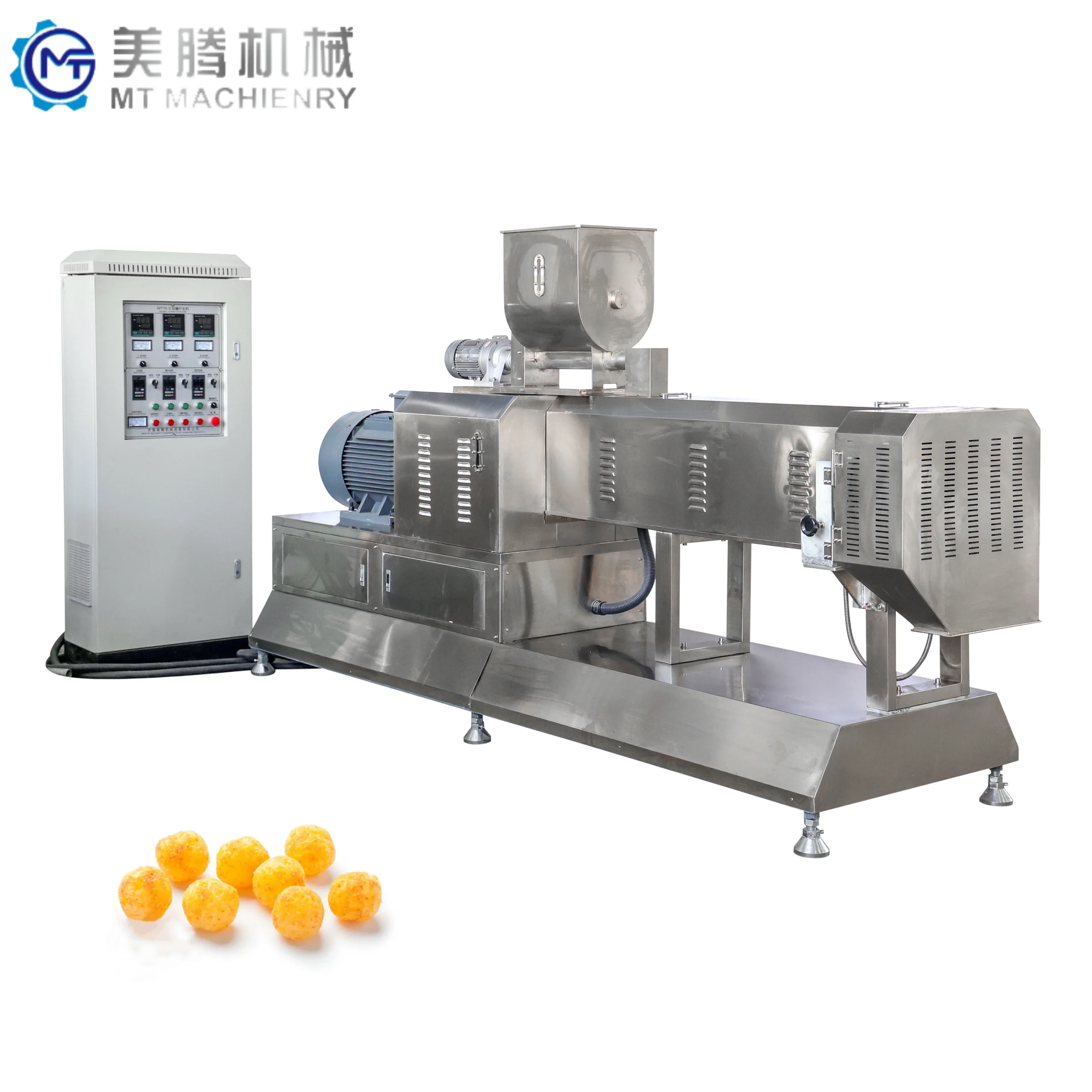
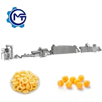
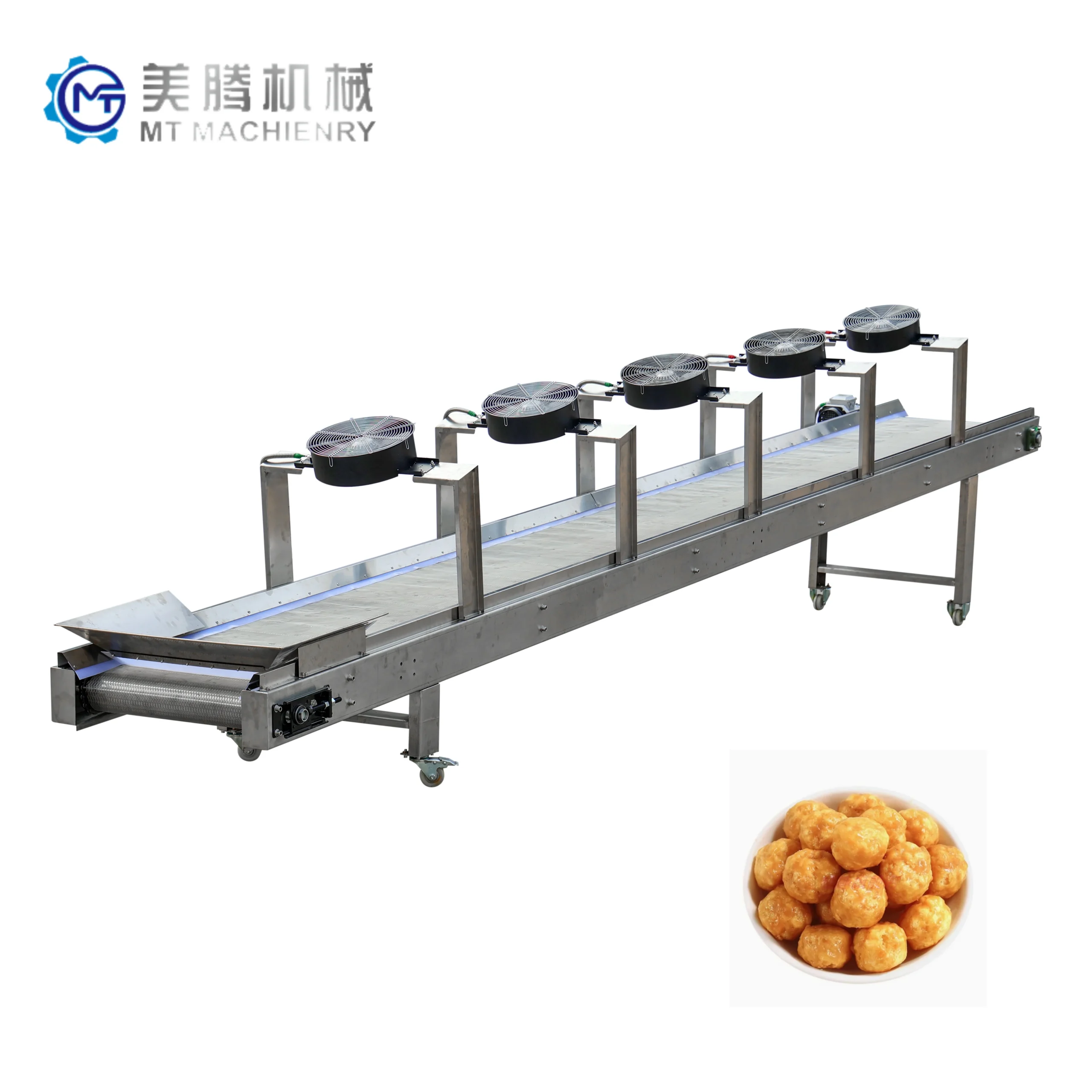
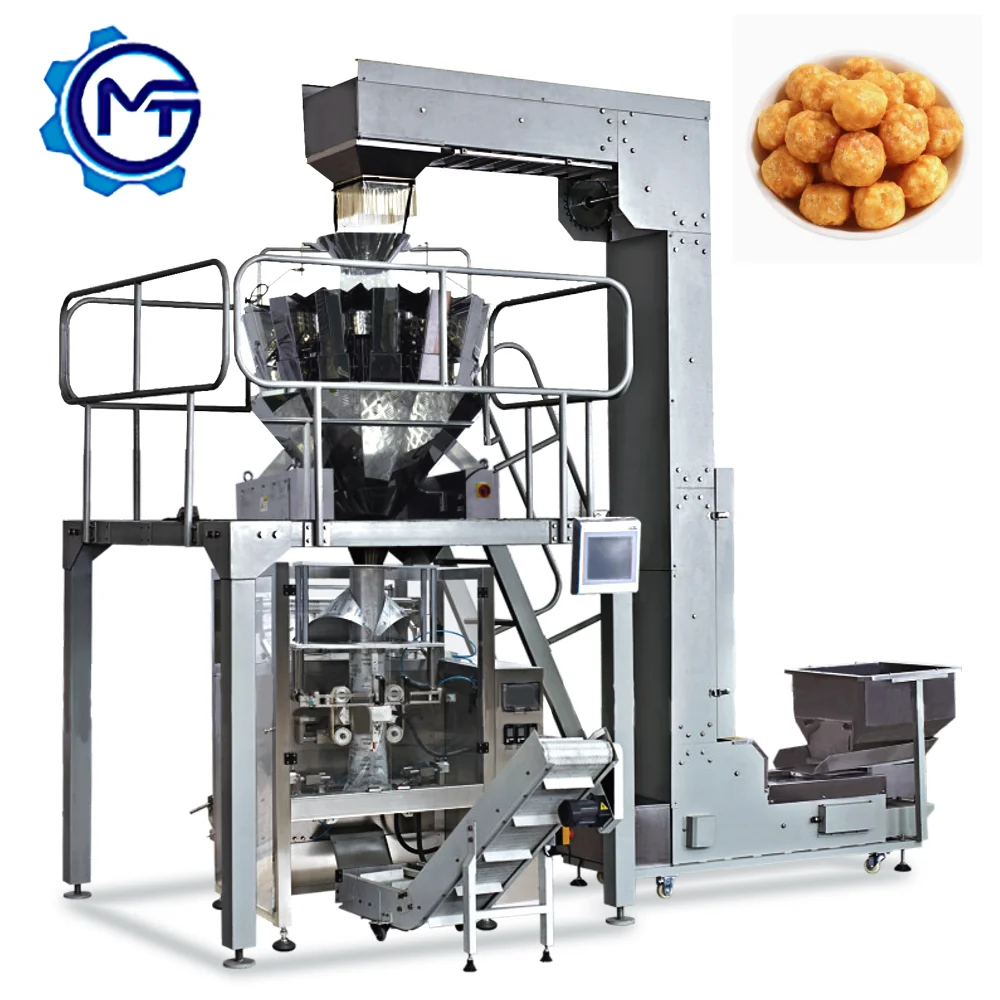
MT65 / MT70 / MT85 / MT100 Twin Screw Extruder Puffed Snack Production Line, 130–240 kW installed power, interchangeable die system — engineered as a complete turnkey layout where extrusion, drying, and double-drum flavoring stations are throughput-matched to prevent bottlenecks across the entire line.
- Screw configuration and die design specified to your raw material and target product shape, verified through in-house trial runs before shipment
- Core-filling module available to expand your product range on a single extruder platform without separate line investment
- From line layout and capacity calculation through on-site commissioning, operator training, and ongoing wear parts supply — one supplier covers every phase of the project
Description
Throughput-Matched Integration — Every station on the MT65 through MT100 puffed snack lines is sized to the extruder’s actual output on your raw material, not its nameplate rating.
Technical Specifications
| Parameter | Value |
|---|---|
| Model | MT65 / MT70 / MT85 / MT100 |
| Product Type | Twin Screw Extruder Puffed Snack Production Line |
| Screw Configuration | Twin screw, configuration matched to raw material and target product |
| Installed Power | MT65: 130 kW; MT70: 180 kW; MT85: 220 kW; MT100: 240 kW |
| Real Consumption | MT65: 95 kW; MT70: 120 kW; MT85: 130 kW; MT100: 160 kW |
| Output Capacity | MT65: 120–150 kg/h; MT70: 200–300 kg/h; MT85: 300–500 kg/h; MT100: 600–800 kg/h (basis not stated in source) |
| Control System | Frequency speed controlling system |
| Line Stations | Material batching, extruding, drying, coating/flavoring, cooling, packing, stacking |
| Die Configuration | Interchangeable dies for cheese ball, tube, stick, ring, fruit loop, star, wheel, flower, heart shapes |
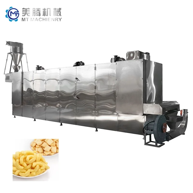
| Heating Source (Dryer) | Electric / Steam / Gas, configurable to local utility conditions |
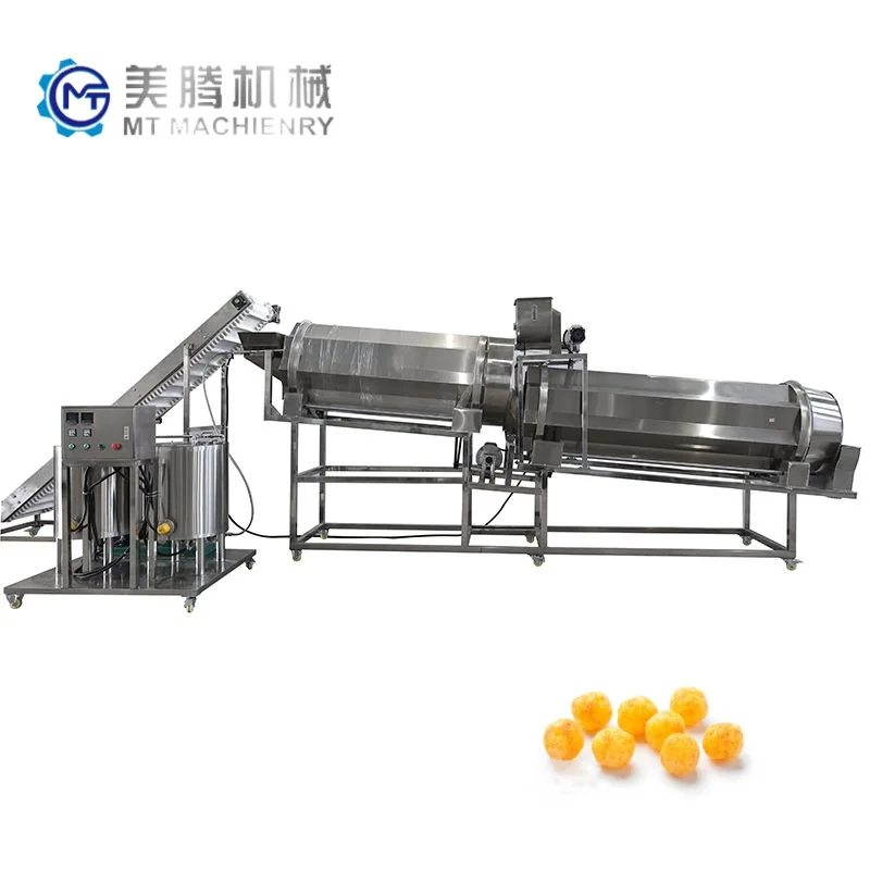
| Flavoring System | Double drum flavoring line with sugar melting and spraying nozzle |
| Core Filling Option | Available with added core filling machine and cutting machine |
| Raw Materials | Corn, rice, wheat, oat, barley flour |
| Warranty | 1 year |
| Delivery Time | Standard line: 20 working days; with packing and stacking: ~35 working days |
| Certification | CE, ISO |
Application Suitability
| Application | Material or Output |
|---|---|
| Cheese ball and ring snack production | Corn flour and rice flour blends with oil and seasoning coating |
| Core-filled extruded snacks | Wheat and oat flour shells with cream, chocolate, or fruit paste centers |
| Breakfast cereal formats (fruit loops, stars) | Corn, wheat, and barley flour with sugar glazing |
| Fortified extruded shapes for nutrition programs | Rice and corn flour blends with added vitamin and mineral premix |
| 2D and 3D pellet snack precursors | Potato starch and corn flour blends for secondary frying or baking |
Why Nominal Line Capacity Fails on the Factory Floor
A puffed snack production line turnkey quoted at a clean number on a spec sheet often cannot sustain that figure once your actual flour blend and local humidity enter the barrel. Capacity must be verified on the buyer’s raw material, not the builder’s reference sample.
I spent weeks on-site in South Asia watching a corn extrusion line produce dense, under-expanded pellets because the local maize had a noticeably lower starch fraction than the test material used back at the factory. The screw profile and temperature curve had to be rebuilt from scratch. When the line was finally tuned, throughput settled well below the original brochure figure, but product texture was correct and the client’s packaging equipment could actually keep up. [NEED_CITE: raw material starch content and moisture variability across growing regions]
Barrel Zones and Shear Control Across the Screw Length
The twin-screw extruder section of this puffed snack production line turnkey is built with multiple independently heated barrel zones. Each zone can be set to a different temperature so that the material progresses from gentle blending and hydration through to high-shear cooking and expansion at the die face. Screw elements are selected and sequenced based on the buyer’s flour type and target snack density, meaning the same MT85 platform can run a light, open-cell corn puff or a dense, crunchy wheat ring simply by reconfiguring the screw profile and die plate.
Matching Dryer Residence Time to Extruder Moisture Evaporation
Downstream of the extruder, the dryer must remove enough residual moisture to stabilize the snack before flavoring. If the dryer is undersized relative to the extruder output, product enters the coating drums too moist and seasoning fails to adhere properly. The dryer on these lines is configured with a heating source — electric, steam, or gas — matched to local utility availability and cost, and its belt length and airflow are scaled to the selected extruder model’s moisture discharge rate. [NEED_CITE: industrial food dryer thermal sizing methods for extruded snacks]
Interpreting the Power and Capacity Band
Installed power climbs from 130 kW on the MT65 to 240 kW on the MT100, while real consumption — what you actually draw during steady-state production — is consistently lower, ranging from 95 kW to 160 kW. This gap matters for transformer sizing and monthly energy cost projections. The output capacity range across the four models spans from small-batch runs suitable for market testing through to continuous high-volume production. Because the exact throughput depends on raw material moisture, starch content, die geometry, and target bulk density, every line should be validated through an in-house trial run before the buyer commits to a shipping date.
The Hidden Cost of Mismatched Downstream Equipment
An extruder that outpaces its flavoring drums creates a pile-up of uncoated product waiting in buffer bins, losing temperature and absorbing ambient moisture. I have watched operators on a poorly matched line hand-feed coating drums because the automated conveyor was sized for a smaller extruder model. The double drum flavoring system on these lines is specified to handle the moisture and temperature envelope coming off the dryer at the selected extruder’s output, preventing that kind of floor-level improvisation. [NEED_CITE: bottleneck analysis in multi-station food processing lines]
Why Source the Full Line from One Integration Point
The batching, extruding, drying, flavoring, cooling, and packing stations are designed as a single system, so throughput is balanced across every transition point rather than left to the buyer to reconcile. Screw and die configurations are specified against the buyer’s raw material sample and target product drawing, not pulled from a generic build library. An in-house testing workshop runs the buyer’s actual flour blend through the extruder before shipment, generating a trial run report that documents expansion ratio, texture, and density. Electrical schematics are prepared with the target market’s voltage and frequency confirmed before the control cabinet is wired. The entire process — from layout proposal through commissioning — is managed by one engineering team rather than handed off between vendors at each station boundary.
Documentation & Verification
- Line layout showing throughput calculations matched across all stations from batching to packing
- Trial run report on your specific corn, rice, or wheat flour blend documenting expansion and density
- Screw and die configuration record tied to your target snack shape and bulk density spec
- Electrical schematic with confirmed voltage, frequency, and control language for your facility
- CE declaration of conformity and ISO certificate for customs and regulatory filing
- Wear parts list identifying screws, dies, and seals with replacement intervals
Installation, Commissioning & Support
- Utility plan specifying dedicated circuits for the extruder’s 95–160 kW real consumption draw
- Foundation and leveling requirements aligned to the line’s station spacing and conveyor runs
- Dryer heating source configured to your facility’s available steam, gas, or electric supply
- On-site screw and die installation with temperature profile tuning on your raw material
- Operator training covering die changeover, flavoring drum adjustment, and daily cleaning routines
- First-set spare screws and dies shipped with the line for initial replacement cycles
What to Include with Your Inquiry
Provide the specific flour types and blends you intend to run, along with any available starch and moisture analysis from your local supplier. Include your target daily output, workshop floor dimensions, and ceiling height so the line layout can be drafted to your space. Confirm your facility’s voltage, phase, and frequency, and note the preferred language for the control interface.
Frequently Asked Questions
Q: How is the output capacity verified against my specific raw material and recipe?
A: Before shipment, your raw material sample is run through the extruder in the testing workshop. The trial produces actual product using your flour blend, and the results — expansion, texture, density, and throughput — are documented in a trial run report. This report becomes the baseline for the screw configuration and die selection shipped with your line.
Q: How do you match throughput between extruder, dryer, and flavoring stations to avoid bottlenecks?
A: Each downstream station is sized to the moisture discharge and mass flow of the selected extruder model. The dryer belt length and airflow, along with the double drum flavoring capacity, are calculated so that product moves continuously without buffer pile-ups or coating failures caused by temperature loss.
Q: What does the turnkey installation process include for layout and commissioning?
A: The process covers a line layout drawn to your workshop dimensions, utility connection planning for power and heating sources, phased equipment placement, on-site screw and die fitting, temperature profile tuning with your raw material, and operator training on changeover and maintenance routines.
Q: How are voltage, frequency, and control language confirmed before production begins?
A: Your facility’s electrical specifications are collected during the proposal stage and written into the electrical schematic. The control cabinet is wired and labeled to those confirmed values, and the frequency speed controlling system interface is set to your preferred operating language before the line leaves the factory.
Q: What spare wear parts are included and how are replacements supplied later?
A: The initial shipment includes a documented wear parts list identifying screws, dies, and seals specific to your configuration. Replacement parts are manufactured to the same screw and die configuration record, ensuring consistent product quality across subsequent production cycles.
Related products
-

Nueva Línea de Producción de Máquinas de Snacks Inflados Máquina de Hacer Copos de Maíz Extrusora de Doble Tornillo Capacidad de 100-500kg/h Alimentos
¥8,500.00 Select options This product has multiple variants. The options may be chosen on the product page -

Línea de procesamiento de bocadillos inflados completamente automática
¥8,500.00 Select options This product has multiple variants. The options may be chosen on the product page -

Máquina Extrusora de Snacks de Maíz Pequeña de Puffs de Maíz de Doble Tornillo
¥100.00 Select options This product has multiple variants. The options may be chosen on the product page -

Línea de Alimentos de Snacks de Maíz Inflado Equipos de Producción de Bolas de Arroz Infladas
¥10,565.00 Select options This product has multiple variants. The options may be chosen on the product page


