

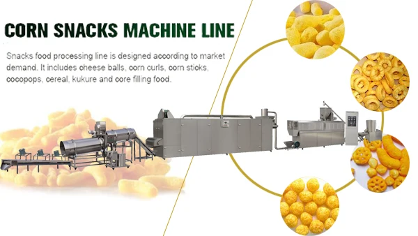
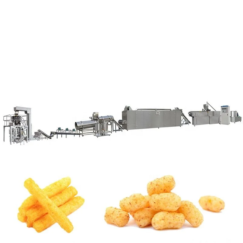
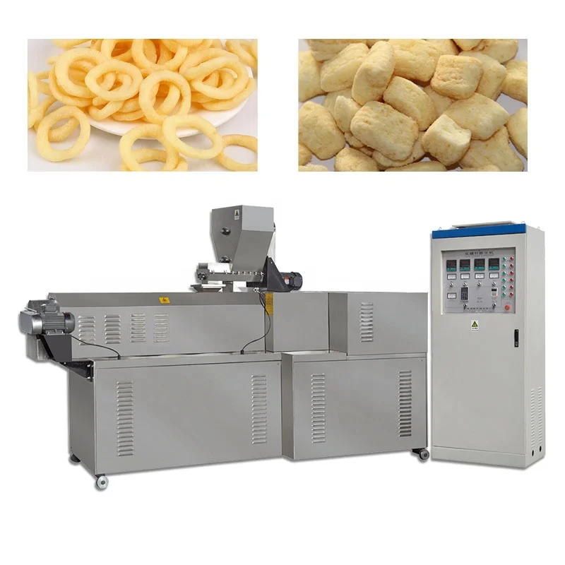
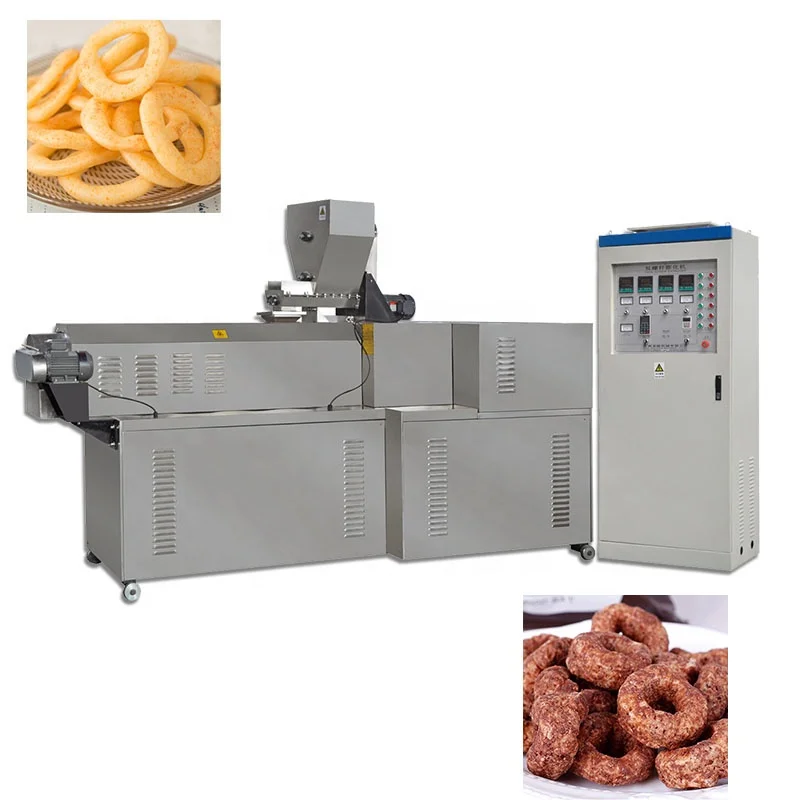
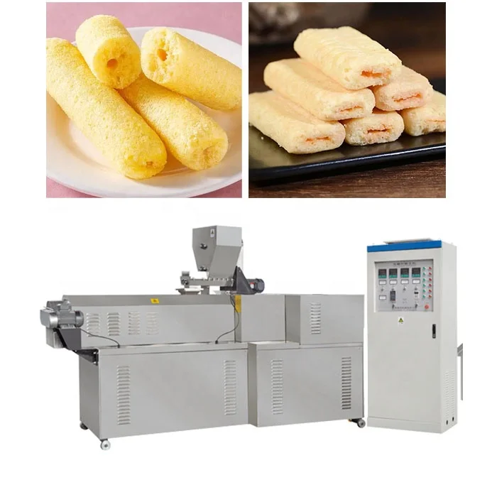
Twin Screw Extruded Puffed Snack Production Line, 380V/50Hz, PLC Control, Food Grade SS304 — engineered for corn puffs, cheese balls and core-filled snacks using rice, millet, buckwheat and corn.
- Screw configuration and die design matched to raw material moisture and target expansion density
- Energy source selectable across electricity, gas, diesel or steam to fit plant utilities
- Flavoring system offered in semi-automatic or automatic for sugar, oil and powder seasoning
Layout, throughput matching and phased commissioning delivered as one turnkey project, with trial runs on your raw material completed in our testing workshop before shipment.
Description
Balanced Station Throughput — Every mixer, dryer, and flavouring drum in this turnkey puffed snack extrusion production line is sized against the extruder’s output curve, eliminating the mid-line material pile-ups that waste raw stock and stall shift targets.
Technical Specifications
| Parameter | Value |
|---|---|
| Product Type | Twin Screw Extruded Puffed Snack Production Line |
| Screw Configuration | Twin screw (co-rotating) |
| Construction Material | Food-grade stainless steel 201/304 |
| Energy Source Options | Electricity, gas, diesel, or steam (configurable) |
| Rated Power | ~100 kW (electricity heating); ~50–60 kW (gas/diesel heating) (basis not stated in source) |
| Control System | PLC-based automation (brand and HMI language to be confirmed) |
| Voltage & Frequency | 380V/50Hz (3-phase) or 220V/50Hz (1-phase); customizable to local standards |
| Line Stations | Mixer → Extruder → Vibrating Cooler → Roasting/Drying Oven → Flavouring → Packing |
| Flavouring Configuration | Semi-automatic or automatic; handles sugar, oil, and powder seasoning |
| Die & Mould System | Changeable dies for multiple shapes (changeover procedure to be confirmed) |
| Standards | CE compliant; ISO certified production |
Application Suitability
| Application Scenario | Target Materials and Output Formats |
|---|---|
| Cheese ball and corn puff manufacturing | Corn grits, rice flour, millet producing hollow or solid spherical snacks |
| Core-filled snack production | Chocolate, cream, or fruit paste centres encased in extruded cereal shells |
| Multi-grain and fortified snack lines | Brown rice, buckwheat, and blended cereals for health-positioned products |
| Breakfast cereal and rice cake formats | Sheet-extruded or pillow-shaped cereal pieces from corn and rice bases |
| Contract packing and private label | Quick die changeovers supporting short runs across multiple SKU shapes |
What a Line Capacity Quote Often Leaves Out About Turnkey Puffed Snack Extrusion Production Line Planning
The extruder sets the pace, but the dryer and flavouring drum determine whether you actually ship saleable product.
I have watched facilities where a twin-screw extruder pushed out several hundred kilograms per hour of hot, moist cheese balls, only for the downstream roasting oven to handle a fraction of that volume. Semi-finished product piled on transfer belts, surface moisture condensed into sticky clumps, and by mid-shift the floor was covered in scrapped material that could not be reworked. The turnkey puffed snack extrusion production line only functions when every station is calculated against the same throughput baseline, not when individual machines are ordered by catalogue capacity. [NEED_CITE: principles of line balancing in continuous food processing]
Layout Planning That Starts From the Packing End
Designing a snack line backwards from the packing station forces every upstream decision to justify itself against a real dispatch target. When we calculate the roasting oven’s belt area, we factor in the moisture drop required between the extruder die exit and the flavouring drum entry point. A cheese ball leaving the die at high moisture content needs sufficient dwell time in the oven to reach the texture and shelf-stability the market expects, and that dwell time directly dictates the oven’s physical length and energy input.
Utility Infrastructure Matching Across Every Station
A complete extrusion project requires coordinated utility planning long before the first crate arrives on site. The extruder alone draws substantial power for barrel heating zones and the main drive motor, while gas-fired or steam-heated dryers demand separate supply lines, pressure regulators, and exhaust routing. Compressed air feeds pneumatic actuators on the vibratory cooler and packing interfaces. When these utility loads are mapped during the layout phase rather than discovered during commissioning, the installation schedule holds and the first production run yields consistent product.
How Screw Configuration and Die Geometry Shape the Final Snack
The twin-screw extruder’s barrel is divided into multiple heating and cooling zones, each independently controlled to manage the starch gelatinisation curve as raw material travels from feed inlet to die plate. The screw element sequence — conveying sections, kneading blocks, and reverse-flight elements — determines shear intensity, residence time, and the degree of mechanical energy transferred into the dough. Die aperture size and land length then govern expansion ratio at the moment the superheated moisture flashes off, which is what gives a cheese ball its characteristic crunch or a core-filled pillow its sealed shell. Changing from a spherical cheese ball die to a sheet die for cereal production requires matching screw profile adjustments so that dough rheology stays within the expansion window the target format demands. [NEED_CITE: twin-screw extrusion rheology and die design principles]
The Hidden Cost of Mismatched Downstream Equipment
Ordering an extruder as a standalone machine and sourcing the dryer and flavouring system separately almost always creates a capacity gap that only reveals itself under full production load. The extruder runs at its rated output, but the roasting oven cannot extract moisture fast enough, forcing operators to throttle extruder speed down and accept lower line utilisation. Flavouring drums that are undersized tumble product too aggressively, breaking fragile puffed shapes and generating excess fines that the packing line then has to screen out. These mismatches compound: lower extruder speed means higher per-kilogram energy cost, while broken product increases raw material waste and reduces saleable yield. [NEED_CITE: throughput bottleneck effects in multi-stage food processing lines]
Why Procuring the Full Line From One Supplier Changes the Project Outcome
Sourcing the entire line — from batching mixer through extrusion, drying, flavouring, and packing — under a single supply contract means one engineering team carries responsibility for throughput continuity across every transfer point. Screw configuration and die design are specified against your actual raw material formulation and target product density, not pulled from a generic build sheet. An in-house testing workshop runs trial production on your supplied ingredients before shipment, generating a documented report that confirms expansion ratio, texture, and flavouring adhesion under controlled conditions. Electrical schematics arrive with voltage and frequency locked to your facility’s grid specification, and the control system’s HMI language is set before the panel is wired. Installation and commissioning follow a phased schedule where each station is verified independently before the full line is started under continuous load.
Documentation & Verification
- Line layout drawing with throughput calculation showing matched capacity at each station
- Screw element sequence and die configuration record specific to your raw material formulation
- Electrical schematic with confirmed voltage, frequency, and control language for your market
- Trial run report from in-house testing workshop using your supplied ingredients before dispatch
- CE declaration of conformity and ISO certification documentation for customs and regulatory filing
- Operation and maintenance manual with wear parts list and recommended replacement intervals
Installation, Commissioning & Support
- Foundation and floor loading plan accounting for extruder vibration and dryer thermal expansion
- Dedicated electrical circuits sized for the ~100 kW extruder heater load and dryer energy source
- Modular station delivery allowing phased positioning before inter-station conveyor alignment
- First-run parameter logging across barrel zones, screw speed, and dryer temperature during commissioning
- Operator training covering die changeover, screw cleaning, and PLC fault code interpretation
- Wear parts inventory covering screw elements, die inserts, and dryer belt sections for initial production months
What We Need to Engineer Your Line Layout
To produce an accurate layout and throughput calculation, share your target product format — whether solid cheese balls, core-filled pillows, or sheet cereal — along with the primary raw materials and their typical moisture content at batching. Provide your available floor space dimensions including ceiling height, and confirm the electrical supply voltage and frequency at your facility. If you have existing upstream milling or downstream packing equipment that the new line must integrate with, include those machine specifications so transfer heights and belt speeds can be matched from the start.
Frequently Asked Questions
Q: How is throughput verified across every station to prevent line bottlenecks?
A: Each station’s capacity is calculated against the extruder’s output curve for your specific formulation, accounting for moisture loss in the dryer and tumble time in the flavouring drum. The line layout document shows matched throughput at every transfer point, and a trial run in the testing workshop confirms these calculations on your actual raw material before any equipment ships.
Q: What utility planning is required for the full line footprint?
A: The extruder requires a dedicated high-amperage circuit for barrel heating zones and the main drive. Gas or steam-fired dryers need supply lines, pressure regulation, and exhaust ducting routed to your facility’s ventilation system. Compressed air feeds pneumatic actuators throughout the line. All utility connection points and load requirements are detailed in the electrical schematic and installation documentation provided before delivery.
Q: How is the phased installation and commissioning schedule structured?
A: Stations are positioned and anchored individually, then inter-station conveyors are aligned and calibrated. Each machine is tested independently — extruder barrel zones verified, dryer temperature uniformity mapped, flavouring drum rotation balanced — before the full line runs under continuous load. Operator training runs parallel to commissioning so your team gains hands-on experience during parameter fine-tuning.
Q: Can the screw configuration and die design be matched to our raw material before shipment?
A: Yes. You supply a sample of your raw material blend, and our testing workshop runs trial extrusion with different screw element sequences and die geometries. The trial report documents expansion ratio, product density, and surface texture, and the final screw and die configuration is locked based on these results before the extruder is assembled for shipping.
Q: What operator training and documentation is included with on-site commissioning?
A: Training covers daily startup and shutdown sequences, die and screw changeover procedures, PLC navigation for recipe storage and fault diagnostics, and routine maintenance including lubrication points and wear part inspection intervals. The operation manual includes illustrated troubleshooting guides, and a complete wear parts list with reorder codes is provided so your procurement team can maintain stock levels independently.
Related products
-

Automatic Rice Crispies Extruder Machine/Chocolate Corn Flakes Extrusion Plant/wheat Flaking Snacks Production Line
¥8,500.00 Select options This product has multiple variants. The options may be chosen on the product page -

Automatic Puffed Food Snack Machine Electric Corn Puffs Snacks Making Machinery New Condition Flavorful Puff Snack Production
¥7,550.00 Select options This product has multiple variants. The options may be chosen on the product page -

Stainless Steel Corn Puff Cake Making Machine Corn Snack Food Machines Top Selling Snacks Machine
¥8,560.00 Select options This product has multiple variants. The options may be chosen on the product page -

Puff Corn Extruder Machine Puffed Core Filled Snack Food Production Line Machine
¥8,500.00 Select options This product has multiple variants. The options may be chosen on the product page


