

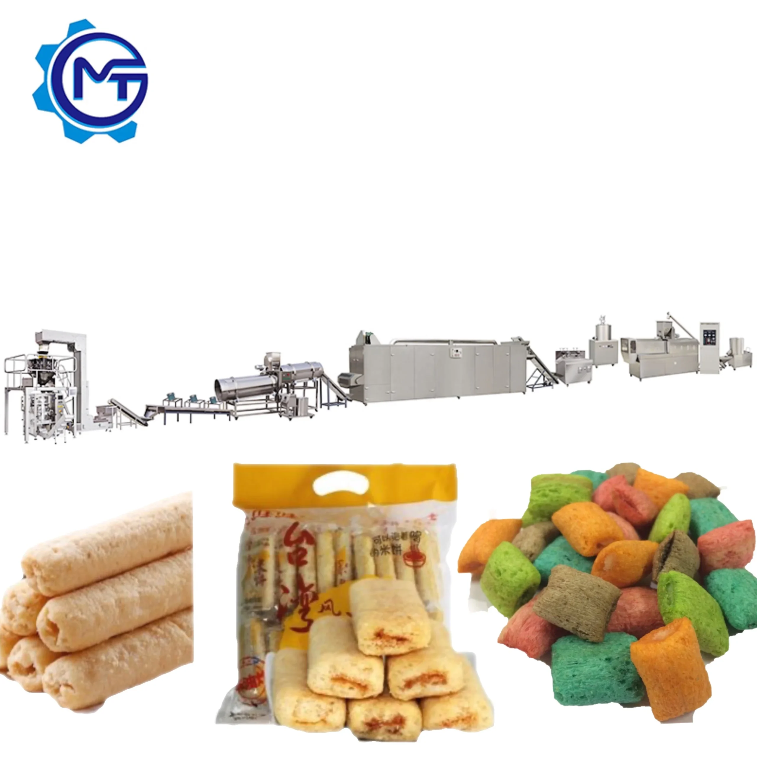
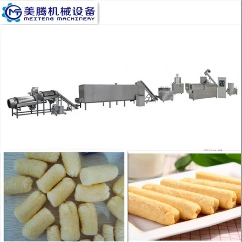

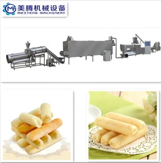
MT70 / MT85 / MT75 Twin Screw Extruder Plant for Puffed Snacks, 130–220 kW, Interchangeable Die System — configured as a turnkey food extrusion processing line from mixing through packing.
- Twin-screw extrusion with screw configuration and die design matched to your cereal flour blend, controlling moisture, shear and expansion for consistent puff density and texture across ball, tube, stick, ring and fruit loop shapes
- Gas or electric dryer scaled to extruder output, with coating and cooling stations throughput-matched to prevent downstream bottlenecks
One-supplier turnkey scope includes line layout, capacity calculation, in-house trial runs on your raw material before shipment, and on-site commissioning with operator training.
Description
Integrated Line Matching — A twin screw extruder plant for puffed snacks where the extruder, dryer, coating drum, and packing station are sized to one throughput target rather than assembled from unrelated vendors, eliminating the hidden bottleneck cost that stalls most new snack lines.
Technical Specifications
| Parameter | Value |
|---|---|
| Product Type | Twin Screw Extruder Plant for Puffed Snacks |
| Extruder Models Available | MT70 / MT85 / MT75 |
| Screw Type | Twin Screw |
| MT70 Installed Power | 130 kW |
| MT70 Power Consumption | 95 kW |
| MT70 Output Capacity | 100–120 kg/h (basis not stated in source — confirm raw material and moisture) |
| MT70 Overall Dimensions | 21 × 1.5 × 2.2 m |
| MT85 Installed Power | 180 kW |
| MT85 Power Consumption | 120 kW |
| MT85 Output Capacity | 200–300 kg/h (basis not stated in source — confirm raw material and moisture) |
| MT85 Overall Dimensions | 25 × 1.5 × 2.2 m |
| MT75 Installed Power | 220 kW |
| MT75 Power Consumption | 130 kW |
| MT75 Output Capacity | 300–500 kg/h (basis not stated in source — confirm raw material and moisture) |
| MT75 Overall Dimensions | 28 × 1.5 × 2.2 m |
| Line Stations | Mixing → Extruding → Roasting/Drying → Sugar-coating/Flavoring → Cooling → Packing |
| Heating Source (Dryer) | Gas or Electric |
| Coating System | Double tumble for sugar melting, elevator, coating drum, spraying nozzle |
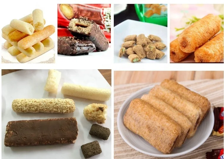
| Die Configuration | Interchangeable moulds for ball, tube, stick, ring, fruit loop, star, wheel, flower, heart shapes |
| Control System | Available with PLC or MCC control (source value — verify against manufacturer catalog) |
| Assembly State | Complete turnkey line |
Application Suitability
| Application | Material or Output |
|---|---|
| Puffed corn snack production | Corn flour, corn grits at controlled moisture |
| Rice-based extruded snacks | Rice flour and rice grits blends |
| Multi-grain cereal snacks | Wheat, oat, and barley flour combinations |
| Shaped children’s snacks | Cereal flour blends producing fruit loops, stars, wheels |
| Savory puffed snack formats | Cereal-based raw materials producing sticks, rings, cheese balls |
Why Your Snack Line Stalls at Half Its Nameplate Capacity
A puffed snacks extrusion production line turnkey quote that reads "300 kg/h" tells you nothing about what happens when your specific corn-to-rice flour ratio hits the barrel at your local ambient humidity.
I learned this the hard way in Nigeria. A customer switched from corn grits to a locally sourced sorghum flour blend after the line was already configured. The screw combination was not adjusted. On start-up, output dropped to roughly half the nameplate figure, and every downstream station — dryer, coating drum, cooling conveyor — was suddenly oversized for the actual feed rate. Commissioning stretched two weeks beyond plan because the entire line rhythm had to be rebalanced from scratch. That kind of mismatch is not rare in snack extrusion projects, and it almost always traces back to a layout that was designed around a catalogue number rather than a real material [NEED_CITE: twin screw extrusion throughput dependency on raw material composition and moisture].
The only reliable way to confirm a puffed snacks extrusion production line turnkey capacity figure is to run the buyer’s actual flour blend through the extruder before the line ships.
Throughput Matching Across Every Station
A snack extrusion line fails when one station forces every other station to idle. If the MT85 extruder pushes material at a rate the dryer cannot handle, product piles up wet and under-crisped. If the coating drum is undersized, flavored product backs up and the entire puffed snacks extrusion production line turnkey sequence stutters. The layout has to be calculated backward from packing speed, through cooling, coating, drying, and finally extrusion, so that each station’s rated throughput aligns with the next.
Screw Configuration Is Not a Copy-Paste Decision
The twin screw design gives the operator control over shear, residence time, and melt temperature by rearranging screw elements along the barrel. A screw combination optimized for pure corn flour will behave differently on a blend that includes oat or barley, because each starch gelatinises at a different temperature and moisture window. The configuration record for this line specifies which element sequence is loaded for the buyer’s target recipe, and the in-house testing workshop validates that combination before dispatch [NEED_CITE: screw element arrangement and starch gelatinisation in twin screw extrusion].
Reading the Numbers That Matter
The three extruder models span installed power from 130 kW on the MT70 up to 220 kW on the MT75, and overall line length from 21 m to 28 m. Power consumption figures — 95 kW, 120 kW, and 130 kW respectively — represent the running load rather than the peak draw, which matters for sizing your main breaker and transformer. The dryer is available with gas or electric heating; gas units typically respond faster to temperature changes during product changeover, while electric units simplify utility planning where gas supply is unreliable. Die interchangeability across nine shape families means one mechanical line can serve several SKUs without a second extruder investment. The control system is configurable between PLC and MCC architectures depending on how much recipe automation the buyer wants versus manual override capability.
The Hidden Cost of a Mismatched Line Configuration
When the dryer capacity lags behind the extruder output, product exits the barrel correctly expanded but then sits in a humid drying chamber too long, losing the crispness the market expects. When the coating drum is undersized, sugar or seasoning coverage becomes uneven, and rejected product climbs. None of these problems show up in a quotation that lists only the extruder model and a headline output number. The financial hit comes later, in lost production days, rework labor, and customer complaints about texture or flavor consistency that trace back to a bottleneck nobody designed for [NEED_CITE: downstream bottleneck effects in snack extrusion processing lines].
Why Procure This Line Here
Complete line stations from mixing through packing are supplied under one responsibility, so throughput calculations are done once, coherently, rather than stitched together from separate vendor datasheets. The screw configuration and die set are specified against the buyer’s actual flour blend and target shape, not copied from a generic build. Every line goes through an in-house testing workshop where the buyer’s raw material is extruded, dried, and coated before shipment, producing a trial run report that confirms real throughput. The documentation package includes an electrical schematic with voltage, frequency, and control language locked to the destination market, preventing commissioning delays caused by mismatched panels. Twin screw expertise covers the full spectrum of puffed snack formats — corn sticks, cheese balls, fruit loops, rings — so the same engineering team that designs the line also understands the product the line must deliver.
Documentation & Verification
- Line layout drawing showing station-by-station throughput balance for your selected model
- Trial run report extruding your flour blend through the configured screw combination before dispatch
- Screw and die configuration record listing every included mould set and its corresponding shape
- Electrical schematic confirming voltage, frequency, and control panel language for your country
- Factory test record documenting running parameters on your target recipe prior to crating
Installation, Commissioning & Support
- Foundation plan scaled to the selected line length of 21 m to 28 m with anchor bolt layout
- Dedicated circuit sizing based on installed power of 130 kW to 220 kW depending on model
- On-site assembly of dryer, coating drum, and cooling conveyor with belt tension and alignment checks
- First-run commissioning verifying barrel temperature profile, die pressure, and product expansion against trial run data
- Operator training covering screw element changeover, die swap procedure, and control system recipe entry
- Wear parts list specifying screw sections, die plates, and dryer belt segments with recommended replacement intervals
What to Include in Your Inquiry
Share your target flour blend and moisture content, the snack shapes you plan to run, and your daily production target in kilograms so the correct model can be selected and the dryer and coating drum sized accordingly. Confirm your workshop’s available length and ceiling height, along with local voltage and frequency, so the electrical package is built right the first time. If you have existing packing or warehousing equipment the new line must feed into, include those details so the cooling conveyor discharge height and packing station interface are coordinated before fabrication.
Frequently Asked Questions
Q: How is line capacity verified on my specific raw material blend before shipment?
A: Your flour blend is shipped to the testing workshop, where it is extruded through the configured screw combination and run through the dryer and coating drum. A trial run report documents actual output, expansion ratio, and product texture. That report accompanies the line and becomes the baseline for on-site commissioning.
Q: How do you match throughput between the extruder, dryer, and coating station?
A: The layout is calculated from packing speed backward through cooling, coating, drying, and extrusion. Each station’s capacity is specified so the extruder never overfeeds the dryer and the coating drum never starves. The matched-throughput calculation is included in the line layout document provided before order confirmation.
Q: What factory layout and utility planning is included in the turnkey scope?
A: You receive a scaled line drawing showing equipment placement, utility connection points for water, gas, electricity, and compressed air, and material flow direction. The drawing accounts for the selected model’s overall dimensions, operator walkways, and maintenance access clearances specific to your workshop footprint.
Q: How is voltage, frequency, and control system language confirmed for my country?
A: During the pre-order phase, the electrical schematic is prepared with your local voltage and frequency, and the control panel language is set to your operator preference. The schematic is sent for approval before production begins, so the panel that arrives on site matches your electrical infrastructure without modification [NEED_CITE: voltage and frequency standards by export market].
Q: What does the installation, commissioning, and operator training schedule look like on site?
A: Engineers arrive for mechanical assembly, utility connection, and first-run testing. Commissioning covers barrel temperature profiling, die pressure adjustment, and product shape verification against the trial run report. Operator training includes screw element changeover, die swaps, and control system recipe entry, followed by a supervised production run before handover.
Related products
-

Automatic Corn Crisps Extruder Production Machine for Maize Chips and Corn Sticks New Condition
¥8,000.00 Select options This product has multiple variants. The options may be chosen on the product page -

Fully automatic puff snack processing line
¥8,500.00 Select options This product has multiple variants. The options may be chosen on the product page -

Hot Sale Corn Snack Extruder Puffed Snacks Production Machine Corn Puffs Making Machine
¥20,000.00 Select options This product has multiple variants. The options may be chosen on the product page -

New Puffed Snack Food Machine Production Line Corn Flake Puff Corn Making Machine Twin Screw Extruder 100-500kg/h Capacity Food
¥8,500.00 Select options This product has multiple variants. The options may be chosen on the product page


