

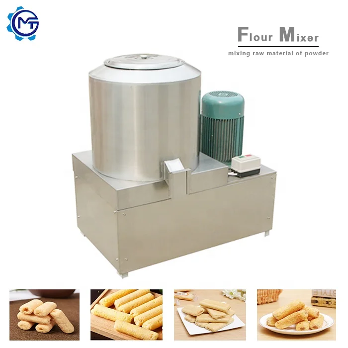
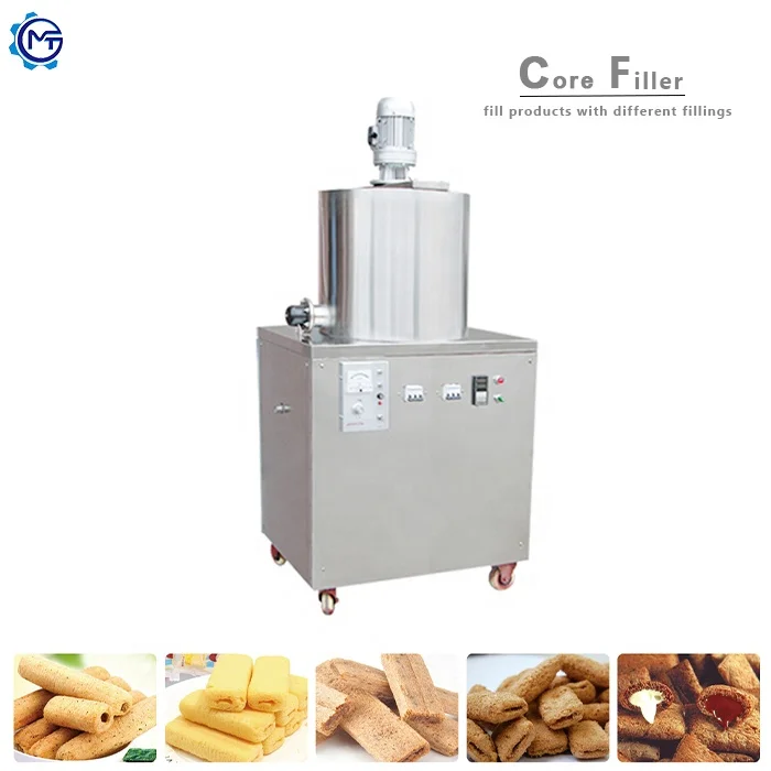
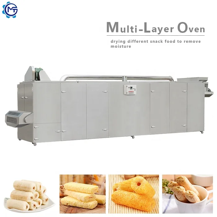
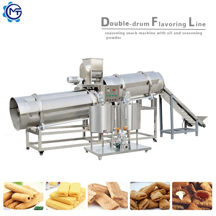
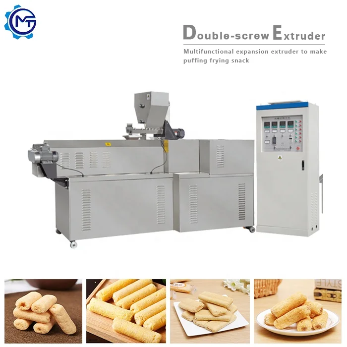
MT70 Twin Screw Extrusion Puffed Snack Production Line, 130 kW Installed Power, PLC & MCC Control — engineered as a complete turnkey project with throughput matched across every station from batching to packing.
- Die configurations produce ball, tube, stick, ring, fruit loop, star and heart shapes from corn, rice, wheat and barley flour
- Gas or electric dryer sized to extruder output, eliminating downstream bottlenecks
- Double tumble sugar coating system calibrated for consistent coverage at full line speed
Trial runs on your raw material are completed in our testing workshop before shipment, validating capacity and texture against your actual recipe.
Description
Complete line engineering — throughput matched from batching through extrusion to packing under one supplier, eliminating the bottleneck risk of assembling a puffed snack extrusion production line turnkey from separate vendors.
Technical Specifications
| Parameter | Value |
|---|---|
| Product Type | Twin Screw Extrusion Puffed Snack Production Line |
| Model Options | MT70 / MT85 / MT75 |
| Screw Type | Twin Screw |
| Installed Power (MT70) | 130 kW |
| Installed Power (MT85) | 180 kW |
| Installed Power (MT75) | 220 kW |
| Power Consumption (MT70) | 95 kW |
| Power Consumption (MT85) | 120 kW |
| Power Consumption (MT75) | 130 kW |
| Output Capacity (MT70) | 100–120 kg/hr (basis not stated in source — confirm raw material, moisture and die shape) |
| Output Capacity (MT85) | 200–300 kg/hr (basis not stated in source — confirm raw material, moisture and die shape) |
| Output Capacity (MT75) | 300–500 kg/hr (basis not stated in source — confirm raw material, moisture and die shape) |
| Overall Dimensions (MT70) | 21 × 1.5 × 2.2 m |
| Overall Dimensions (MT85) | 25 × 1.5 × 2.2 m |
| Overall Dimensions (MT75) | 28 × 1.5 × 2.2 m |
| Control System | PLC and MCC |
| Die Configuration | Interchangeable — ball, tube, stick, ring, fruit loop, star, wheel, flower, heart |
| Heating Source (Dryer) | Gas or Electric |
| Coating System | Double tumble sugar melter, elevator, coating drum, spraying nozzle |
| Line Stations | Mixing → Extruding → Drying → Sugar-coating / Flavouring → Cooling → Packing |
| Raw Materials | Corn, rice, wheat, oat, barley flour |
| Assembly State | Turnkey complete line |
| Standards | CE, ISO |
Application Suitability
| Application | Material or Output |
|---|---|
| Cheese ball and ring snacks | Corn flour and rice flour blends |
| Fruit loop and star-shaped cereals | Wheat, oat and barley flour mixes |
| Tube and stick extruded snacks | Corn and rice grits with seasoning |
| Heart and flower novelty shapes | Multi-grain flour formulations |
| Fortified puffed snacks for nutrition programmes | Blended grain flours with micronutrient premix |
What "Rated Capacity" Actually Means on a Puffed Snack Extrusion Production Line Turnkey
A capacity number is only real when it has been validated on your specific flour blend at your target moisture level.
Too many snack producers receive a line quoted at a nominal output, only to discover during commissioning that the extruder cannot sustain that throughput on their actual recipe. The screw configuration may have been copied from a generic build, the dryer may be undersized for the moisture load your material carries, or the coating drum may not keep pace with extruder discharge. The result is a puffed snack extrusion production line turnkey that runs well below its paper specification [NEED_CITE: twin-screw extrusion throughput validation on buyer raw material]. I once saw a cheese ball line where the drying section was specified for a different product density entirely — the extruder pushed product faster than the dryer could handle, and the factory floor became a staging area for semi-wet product waiting for belt space.
Matching Every Station to One Throughput Target
The core discipline in building a puffed snack extrusion production line turnkey is ensuring that the mixer, extruder, dryer, flavouring drum, cooler and packer all share the same throughput target. When one station is oversized and another undersized, the entire line runs at the pace of its weakest link. Each MT-series extruder model pairs with a dryer and coating system sized to its discharge rate, so material flow remains continuous from batching to final packing without manual buffering between stages.
Validating Capacity Before the Line Leaves the Factory
Running a trial on the buyer’s actual raw material in the testing workshop is what separates a credible capacity claim from a hopeful one. The screw configuration, barrel temperature profile and die selection are adjusted during this trial until texture, expansion ratio and output meet the target specification. The trial run report then becomes part of the shipping documentation, giving the buyer a verified baseline before the equipment arrives on site [NEED_CITE: in-house extrusion trial run documentation standards].
How Screw and Die Choices Shape the Final Snack
The twin-screw design handles a wider range of flour blends and moisture levels than a single-screw equivalent, making it practical to run corn, rice, wheat, oat and barley formulations on the same extruder. The interchangeable die system allows production of ball, tube, stick, ring, fruit loop, star, wheel, flower and heart shapes without changing the extrusion station itself — product diversification happens through die swaps and screw reconfiguration rather than additional capital equipment. Barrel temperature zones and screw element arrangement are set to the specific gelatinisation behaviour of each flour type, controlling expansion and density at the die face.
The Cost of Ignoring Downstream Matching
When the dryer or coating drum is not matched to extruder output, the consequences extend beyond lost throughput. Product queued between stations cools unevenly, causing inconsistent moisture content that affects shelf life and crunch texture. Sugar coating applied to product that has not been properly dried leads to clumping and surface defects. These quality issues compound over a production shift, generating waste that erodes the margin on every kilogram of finished snack [NEED_CITE: downstream equipment mismatch effects on extruded snack quality].
Why Source the Full Line From One Engineering Team
Every station on this puffed snack extrusion production line turnkey is specified by the same team that designs the layout, so throughput calculations are consistent from mixer to packer rather than patched together from separate vendor data sheets. The in-house testing workshop runs production trials on your flour blend before dispatch, confirming that screw configuration and die selection produce the target texture and density. Electrical schematics and voltage confirmation are completed during the engineering phase, ensuring the PLC language, frequency and supply voltage match your facility before the control cabinets are wired. Wear parts — screws, dies, seals — are documented with part numbers and lead times so the first replacement cycle is planned before the initial run consumes the original set.
Documentation & Verification
- Line layout drawing with capacity calculation for every station from mixer to packer
- Trial run report on your flour blend produced in the testing workshop before shipment
- Screw and die configuration record matched to your target snack shape and density
- Electrical schematic with voltage, frequency and PLC language confirmed for your facility
- CE declaration of conformity and ISO certificate for the complete line package
- Wear parts list with part numbers and recommended replacement intervals
Installation, Commissioning & Support
- Foundation and utility layout provided for the 21–28 m line footprint depending on model selected
- Power supply confirmed to match 130–220 kW installed capacity with dedicated circuit planning
- Stations shipped in modular sections for sequential assembly and belt alignment on site
- PLC and MCC commissioned with operator interface set to the local language before first production run
- Operator training covers screw configuration changes, die swaps and coating drum calibration
- Spare screw elements, dies and seals supplied with part numbers for reorder planning
Preparing Your Project Brief
To move from inquiry to line configuration, we need your target snack shapes, the flour blend or blends you plan to run, and the hourly output you intend to sustain. Share your facility voltage, frequency and available floor space so the layout and electrical package can be matched from the start. If you have existing upstream or downstream equipment that must integrate with the new line, include those specifications so throughput matching accounts for every station.
Frequently Asked Questions
Q: How is line capacity verified on the buyer’s actual raw material before shipment?
A: The testing workshop runs a production trial using your flour blend at your target moisture level. Screw configuration, barrel temperatures and die selection are adjusted until expansion, density and output meet the specification. A trial run report documenting these results ships with the line.
Q: What does the turnkey scope cover beyond the equipment itself?
A: The scope includes line layout design, throughput calculation across every station, utility planning, on-site installation, commissioning with parameter setting, and operator training covering screw changes, die swaps and coating calibration.
Q: How are voltage, frequency and PLC language confirmed for the target market?
A: During the engineering phase, the electrical team prepares schematics based on your facility supply specification. Voltage, frequency and control language are documented and confirmed before the MCC and PLC cabinets are assembled and wired.
Q: How is throughput matched between extruder, dryer and coating stations?
A: Each station is sized during layout design to the same hourly throughput target. The dryer belt length and heating capacity, coating drum volume and spray rate are all calculated from the extruder discharge rate on your specific recipe.
Q: What spare wear parts come with the first delivery?
A: The initial shipment includes spare screw elements, dies and seals with a documented parts list. Part numbers and estimated replacement intervals are provided so you can plan reorder timing before the first production cycle ends.
Related products
-

Automatic Puffed Food Snack Machine Electric Corn Puffs Snacks Making Machinery New Condition Flavorful Puff Snack Production
¥7,550.00 Select options This product has multiple variants. The options may be chosen on the product page -

Corn Puff Processing Line with Mixer Fryer Baking Oven Automatic High Productivity Grain Products Snack Making Machine
¥8,300.00 Select options This product has multiple variants. The options may be chosen on the product page -

Puffed Snack Food Machine Snack Food Machine Puffed Snack Machine
¥11,050.00 Select options This product has multiple variants. The options may be chosen on the product page -

Automatic Rice Crispies Extruder Machine/Chocolate Corn Flakes Extrusion Plant/wheat Flaking Snacks Production Line
¥8,500.00 Select options This product has multiple variants. The options may be chosen on the product page


