

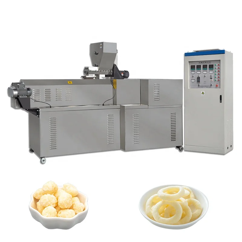
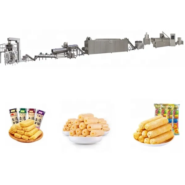
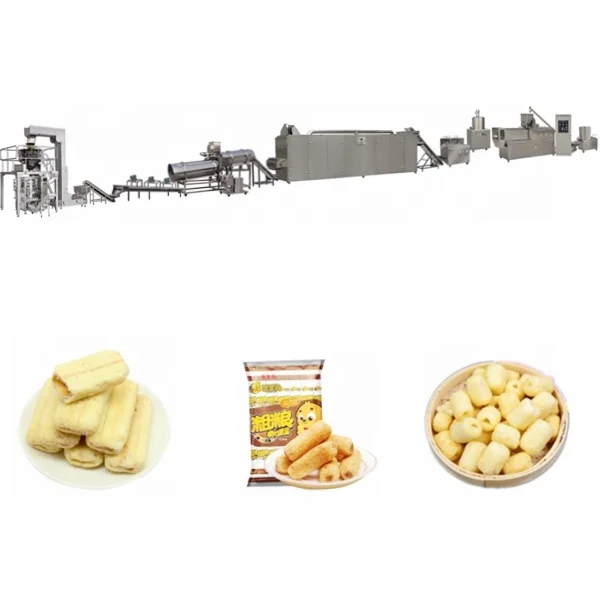
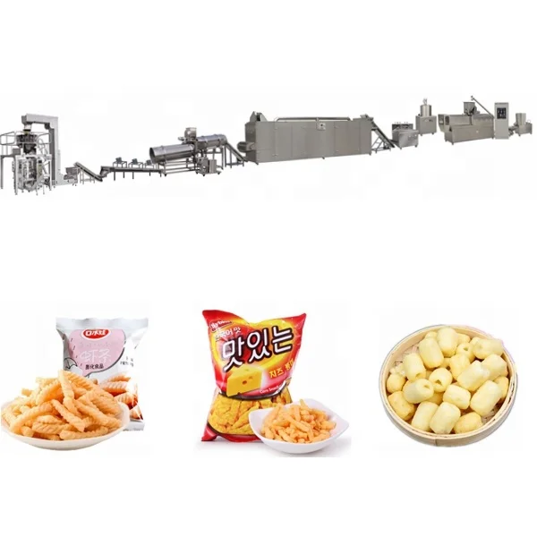
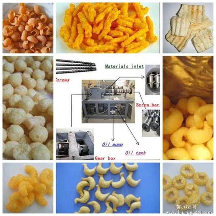
MT70, MT85, MT75 Twin Screw Extrusion Corn Puffs Snack Production Line, 100–500 kg/h, PLC Control — complete turnkey layout from batching through extrusion, drying, coating, cooling and packing under one supplier.
- Screw configuration and die design matched to your raw material and target snack shape, with interchangeable dies for ball, tube, ring, fruit loop, star and wheel profiles
- Twin screw extruder with automatic lubricating and cooling, special-process wear-resistant screws, and gas or electric dryer options
- Coating station features double tumble sugar melting, dedicated elevator and spraying nozzle, throughput-matched to extruder model
Trial runs on your actual raw material are completed in our in-house testing workshop before shipment, so product development starts before installation — not after.
Description
Integrated Turnkey Snack Extrusion Line Engineering — Every station from batching through extrusion, drying, coating, and packing is throughput-calculated against the others, eliminating the mismatch risk that delays commissioning on multi-vendor setups.
Technical Specifications
| Parameter | Value |
|---|---|
| Product Type | Twin Screw Extrusion Corn Puffs Snack Production Line |
| Model | MT70 / MT85 / MT75 |
| Screw Configuration | Twin-screw with automatic lubricating and cooling system |
| Installed Power | MT70 — 130 kW; MT85 — 180 kW; MT75 — 220 kW |
| Power Consumption | MT70 — 95 kW; MT85 — 120 kW; MT75 — 130 kW |
| Output Capacity | MT70 — 100–120 kg/h; MT85 — 200–300 kg/h; MT75 — 300–500 kg/h (basis to be confirmed) |
| Overall Dimensions (L×W×H) | MT70 — 21 × 1.5 × 2.2 m; MT85 — 25 × 1.5 × 2.2 m; MT75 — 28 × 1.5 × 2.2 m |
| Control System | PLC-based with MCC integration available |
| Dryer Heating Source | Gas or electric (selectable) |
| Coating System | Double tumble sugar melting, elevator, coating drum, spraying nozzle |
| Die Options | Interchangeable — ball, tube, stick, ring, fruit loop, star, wheel, flower, heart |
| Raw Material Compatibility | Corn flour, rice flour, wheat flour, oat flour, barley flour, blends |
| Voltage and Frequency | Configurable to local site supply |
| Line Assembly | Complete turnkey project from batching to packing |
Application Suitability
| Application | Material or Output |
|---|---|
| Puffed corn snack production | Corn flour or grits at varying moisture content |
| Cheese ball and ring snack lines | Corn, rice, and wheat flour blends |
| Fruit loop and multi-color cereal snacks | Rice flour, oat flour, and grain blends |
| Star, wheel, and novelty-shaped puffed snacks | Grain-based flours through interchangeable die sets |
| Coated and sugar-glazed extruded snacks | Grain flour base with sugar or savory coating application |
| Breakfast cereal pellet and flake precursors | Corn, wheat, and barley flour formulations |
Why "300 kg/h" Without Context Costs You Weeks of Lost Production
A capacity figure is meaningless unless it names the raw material, moisture level, and product shape it was measured against.
When I first started planning extrusion lines, I trusted the nameplate output and matched downstream equipment to that number. The result: a twin screw extrusion snack production line turnkey setup where the dryer choked on high-moisture dough and the coating drum overflowed because the extruder pushed more volume than the seasoning system could handle. [NEED_CITE: throughput matching principles in continuous food processing lines]. The extruder hit its rated number, but the line as a whole could not. Now before any quotation leaves my desk, I calculate each station’s real throughput against the buyer’s specific grain blend and target shape.
Throughput Matching Across Every Station
The most common failure on a twin screw extrusion snack production line turnkey installation is not the extruder itself — it is the station downstream that cannot keep pace. When the dryer is sized for a nominal capacity rather than the actual moisture load your corn flour blend carries, product backs up before it reaches the coating drum. Each model in this range — MT70, MT85, MT75 — ships with dryer and coating stations calculated to the extruder’s real output envelope, not a generic default.
Screw Configuration Specified to Your Grain Blend
A generic screw profile may extrude corn grits adequately but produce dense, under-expanded output when you switch to a rice-and-oat blend with different starch gelatinisation behaviour. The twin screw extrusion snack production line turnkey approach here involves selecting screw element arrangement, compression ratio, and die geometry against your actual raw material sample. [NEED_CITE: twin screw extrusion screw element configuration for cereal-based formulations]. The in-house testing workshop runs your flour blend before the line ships, so screw and die settings arrive documented rather than discovered during commissioning.
What the Power and Dimension Figures Actually Mean on the Floor
The installed power spread across MT70 (130 kW), MT85 (180 kW), and MT75 (220 kW) reflects not just motor size but the thermal and mechanical energy needed to gelatinise starch at increasing throughputs. Higher installed power on the MT75 supports longer barrel sections and greater shear energy, which matters when processing high-fibre blends like oat and barley that resist expansion. The overall line length — 21 m to 28 m — determines your minimum workshop bay requirement, including clearance for the drying oven and cooling conveyor. The PLC control system coordinates feeder rate, barrel temperature zones, cutter speed, and dryer residence time from a single interface, so batch-to-batch consistency relies on the control logic rather than operator judgment alone. The interchangeable die system means a single extruder platform produces ball, tube, ring, star, and wheel shapes, letting you expand your product catalogue without duplicating capital equipment. [NEED_CITE: relationship between barrel length-to-diameter ratio and starch gelatinisation completeness].
The Cost of Skipping Station-by-Station Verification
I once saw a snack line in a Southeast Asian factory where the extruder ran fine but the coating drum could not keep up — half-finished product piled on the floor between stations because no one had checked the flavouring drum’s cycle time against the extruder’s actual feed rate. [NEED_CITE: consequences of throughput mismatch in continuous food extrusion lines]. The fix took weeks of retrofitting. When dryer heating source selection — gas versus electric — is left to the last minute, you either wait for utility upgrades or burn product in an undersized oven. These are not engineering problems; they are planning oversights that compound into lost production days.
Why Procurement Through a Single Line Integrator Matters
Every station on this twin screw extrusion snack production line turnkey project — batching, extruding, drying, coating, cooling, packing — is specified under one supplier, so throughput figures align by design rather than negotiation between separate vendors. Screw configuration and die design are recorded against your raw material, not copied from a generic build sheet. The testing workshop conducts trial runs on your actual flour blend before shipment, so product development begins in the factory rather than on your floor. Pre-sales consultation carries through to on-site installation, commissioning, and operator training. Voltage, frequency, and control language are confirmed against your facility’s electrical supply before production begins, avoiding the week-long delays I have seen when a 50 Hz control cabinet arrives at a 60 Hz site.
Documentation & Verification
- Line layout drawing with station-by-station throughput calculation for your selected model
- Screw and die configuration record matched to your grain flour blend and target snack shape
- Trial run report from in-house testing workshop using your supplied raw material
- Electrical schematic with confirmed voltage, frequency, and control language before production
- CE declaration of conformity and ISO certificate applicable to the line configuration
Installation, Commissioning & Support
- Line footprint of 21–28 m length requires level concrete floor with drainage for dryer condensate
- Power supply must match confirmed voltage and frequency with dedicated circuit for 130–220 kW installed load
- Stations ship as integrated modules; on-site assembly sequence provided in installation manual
- First-run parameter setting covers feeder rate, barrel zones, cutter speed, and dryer temperature
- Operator training included on-site covering die changeover and PLC control navigation
- Wear parts list with screw and die replacement schedule provided at commissioning
Before You Request a Quotation
Send your raw material specification — the exact flour blend, particle size, and typical moisture content — along with the target snack shape from the die options and your daily production requirement in kilograms. Confirm your facility’s voltage, phase, and frequency, and note the available workshop bay length and ceiling height. If you are replacing an existing line or integrating with upstream milling or downstream packing equipment, include those specifications so the station interfaces can be calculated before the layout is drawn.
Frequently Asked Questions
Q: How is the line capacity verified against my specific raw material and target snack shape before shipment?
A: Your raw material sample is run through the twin screw extruder in the in-house testing workshop with the screw configuration and die specified for your blend. The trial run produces actual output data — expansion ratio, density, and throughput — which is documented in a report before the line ships. This means capacity is confirmed against your corn, rice, or oat flour, not a generic benchmark.
Q: What is the process for matching dryer and coating station throughput to the selected extruder model?
A: Each station is calculated during the layout phase based on the extruder model’s confirmed output on your raw material. The dryer residence time is set to handle the moisture load your blend carries, and the coating drum cycle time is matched to the extruder feed rate. The result is a documented throughput chain where no station bottlenecks the next.
Q: How are screw configuration and die design determined for my raw material?
A: The screw element arrangement and compression ratio are selected based on the starch gelatinisation behaviour of your specific flour blend. Die geometry is matched to the target snack shape — ball, tube, ring, star, or other options — and both are recorded in a configuration sheet. The testing workshop validates the setup before shipment.
Q: What voltage, frequency, and control language options are confirmed before production?
A: Your facility’s electrical supply details are collected during the specification phase and written into the electrical schematic. The PLC control system language is confirmed alongside voltage and frequency so the control cabinet arrives ready to run. This confirmation is documented before the line enters production.
Q: What does the phased installation and commissioning schedule look like?
A: Installation follows a station-by-station sequence across the 21–28 m line footprint, starting with the batching and extrusion section and moving through drying, coating, cooling, and packing. Commissioning includes first-run parameter setting and operator training on die changeover and PLC navigation, with a wear parts schedule handed over at completion.
Related products
-

Puffed Snack Food Machine Snack Food Machine Puffed Snack Machine
¥11,050.00 Select options This product has multiple variants. The options may be chosen on the product page -

Puff Corn Snacks Food Line Puffed Rice Ball Production Making Equipment Machines
¥10,565.00 Select options This product has multiple variants. The options may be chosen on the product page -

Crunchy Puffed Snack Breakfast Cereal Corn Flakes Making Machine
¥1,000.00 Select options This product has multiple variants. The options may be chosen on the product page -

Full Automatic Crispy Maize Chocos Corn Flakes Breakfast Cereals Processing Production Line Industrial Equipment
¥1,000.00 Select options This product has multiple variants. The options may be chosen on the product page


